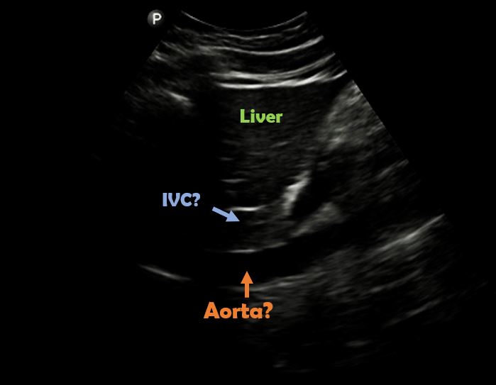
Most novice users of POCUS are under the impression that inferior vena cava (IVC) ultrasound is very easy and it gives all the information about a patient’s volume status. Unfortunately, both are wrong. Proper identification of IVC can be challenging in some patients, and aorta or other structures can be mistaken for it. Basing clinical decisions on POCUS findings (or ‘assumptions’) can potentially lead to patient harm in such situations. Moreover, volume status assessment is complex and involves careful evaluation of the pump, pipes and the leaks as illustrated in Figure 1. IVC (= right atrial pressure estimation) is only a piece of the puzzle and using it in isolation ignoring rest of the data can lead to diagnostic errors. In this post, let us focus on pitfalls involved in correct identification of the IVC.
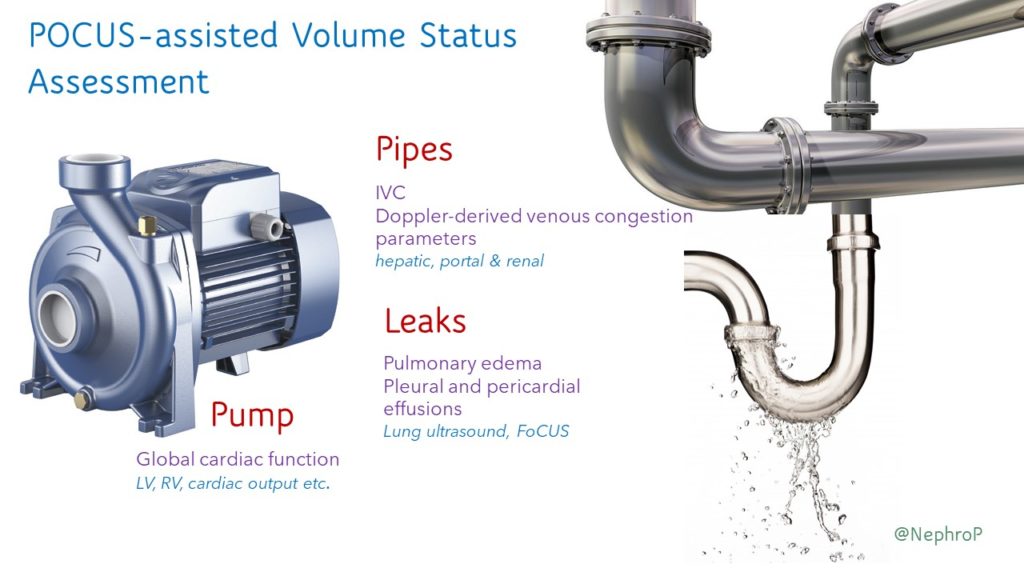
Image acquisition – technique:
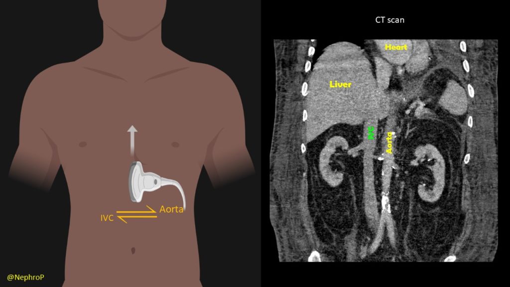
A phased array transducer (= cardiac probe) is commonly used because IVC exam is typically performed as a part of FoCUS. Some providers like to use curvilinear transducer (= abdominal probe), which is equally acceptable. To obtain a longitudinal view of the IVC, the transducer is placed in the subxiphoid window with the orientation marker towards patient’s head and slightly tilted to patient’s right. If it is tilted towards left or the midline, abdominal aorta comes into view [Figure 2]. Always try to visualize the junction of IVC with the right atrium (= slide superiorly till you see the beating structure = heart) and hepatic vein joining the IVC [Figure 3].
Another simple approach when doing FoCUS is that fist get a good subxiphoid 4-chamber view and rotate the transducer counterclockwise till you start seeing the IVC-right atrial junction [Figure 4A]. However, don’t forget to adjust the transducer to align the beam along the long axis of the vessel. Otherwise, the view can be oblique, falsely reducing the diameter of the IVC.
Also note that the right atrium will be on the right of the image if the machine is in cardiac mode (= orientation marker on the right) and on the left if the machine is in the abdominal mode (= orientation marker on the left). It is usually not necessary to perform a color Doppler evaluation of the IVC but if doing so, trying to image at an angle of <600 best demonstrates the color [Figure 4B].
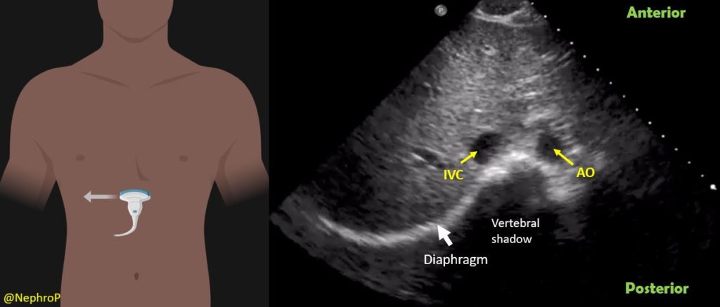
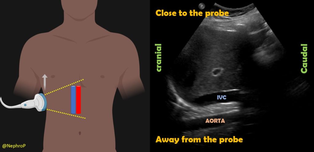
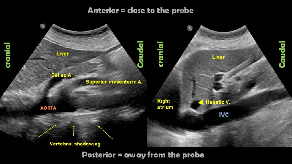
Some physicians first obtain transverse view of the IVC and then rotate the probe to obtain a longitudinal view. There is no absolute benefit of this method over directly obtaining a longitudinal view except in children where assessing IVC-aorta ratio may have a role in evaluation of volume status. It might also be helpful in cases where IVC collapse is preferentially craniocaudal instead of antero-posterior (compare both axes when POCUS findings do not correlate with the overall clinical picture). To obtain this view, the probe is placed in the mid-epigastric region with the orientation marker towards patient’s right. By gently fanning the probe up and down, one can visualize IVC and the aorta anterior to the central shadowing from the vertebral body [Figure 5]. By fanning further up towards the chest, hepatic veins joining the IVC come into view [Figure 6].
When the subxiphoid view is not obtainable because of surgical dressings, distended abdomen etc., longitudinal view of the IVC can also be acquired through right lateral transabdominal coronal approach, also known as the ‘rescue view’. The probe is placed in the right anterior to midaxillary line similar to the placement for evaluating pleural effusion with the orientation marker towards patient’s head. By scanning more anteriorly, the IVC can be visualized running adjacent to the liver and crossing the diaphragm. Aorta is often seen parallel to it (bottom of the image) [Figure 7 and Figure 8].
Pitfalls:
It is very important to differentiate IVC from the aorta to avoid errors in interpretation. Always trace the IVC superiorly and make sure it is joining the right atrium. Also, try to look for the hepatic vein-IVC confluence when possible. Following table summarizes other key differences between these two vessels.
| IVC | Aorta |
| Situated towards right of the abdomen | Left/center |
| Usually compressible in non-intubated patients | Non-compressible |
| Thin walled | Thick walled |
| No anterior branches | Anterior branches present |
| Respiratory variation is present usually | Absent |
| Close to the liver (passes through the liver) | Away from the liver compared to IVC and situated right in front of the vertebral column (= look for prominent vertebral shadowing behind aorta) |
| Joins the right atrium | Does not (continuous with the thoracic aorta) |
Figure 9 demonstrates some of these differences.
Following is an interesting image of the abdominal aorta which can be easily confused with IVC on quick exams. Of note, in a recent twitter poll, only ~40% (of 301 votes) recognized that the vessel is not IVC [Figure 10].
Pulsatility is not a great way to differentiate between IVC and aorta because IVC frequently demonstrates transmitted pulsations. Moreover, in valvular disorders such as severe tricuspid regurgitation, IVC can be very pulsatile mimicking aorta [Figure 11].
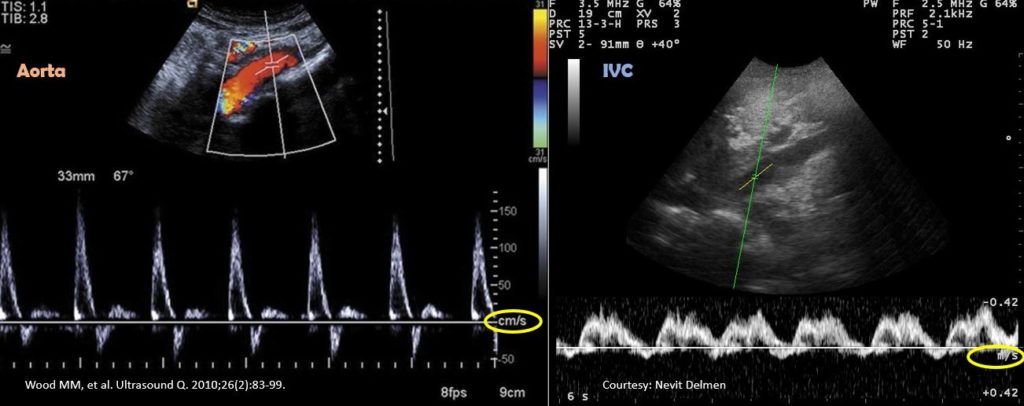
In desperate situations, these vessels can be differentiated using pulsed wave (spectral) Doppler if your machine has the capability. Basically, this mode displays the velocity and direction of the blood flow graphically. Normal aorta has a ‘spiky’ triphasic pattern with high velocities whereas the IVC has more of a ‘M-pattern’ with low velocities [Figure 12]. Note that this is an over-simplified way of remembering this.
IVC can also be confused with caudate lobe of the liver in poor quality, under-gained (too dark) images [Figure 13]. Make sure to adjust the gain (brightness) appropriately for the ambient lighting and follow the rule of visualizing IVC-RA junction before drawing conclusions.
Rarely, duodenum can be confused with IVC as well. Here is an image shared by Pitt Internal Medicine [Figure 14].
On a closer look, one can appreciate the echogenic bowel contents as well as the feeding tube in the duodenum [Figure 15].
Abhilash Koratala, MD, FASN (@NephroP)
Medical College of Wisconsin

Very well demonstrated images, it’s perfect in every way.
thank you!
well done
Excellent, thank you for the sharing
Thank you, it is one of the best i have read
Excellent, thx